
Building an Ethernet Tap
January 19, 2006 at 12:07 AM | categories: electronics, diy | View Comments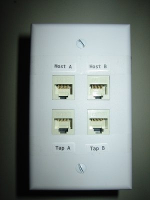
Overview
Recently, I've been teaching myself about network protocols and have also written a network sniffer program: ECSniff which exemplifies the importance of using encryption whenever you transfer sensitive information. Well anyway, ever since I wrote the software, I've wanted to play around with it a bit. Problem is, on todays networks, it gets a bit complicated if you want to see anyone's network traffic but your own. I run an SSH server on my DSL line that has been getting several break in attempts recently (usually someone in Italy trying random usernames and passwords), so I would like to build an Intrusion Detection System to alert me if they ever come back and I'd like it to be a seperate computer from the SSH server. To do this, I need to build an Ethernet Tap to get around the security features built into todays modern switched hubs.
History Lesson
Analyzing network traffic is not as easy as it once was. In the old days we used hubs to connect computers together on a LAN. Hubs are really simple devices. Whatever data comes into it, it simply sends it right back out to all the rest of the ports. Since network packets have the destination encoded in them, the computer that the packet is intended for is then supposed to read it, while all the other computers on the LAN, although they too received the packet, are supposed to ignore it. Talk about a trusting relationship! Would you ever send out your credit card information to everyone in the neighborhood with a post-it-note stuck on top that says "don't read this unless you're Bob"? No!
We've gotten a lot smarter about things since then. Today we use switched hubs instead. Switches are devices that subdivide networks into network segments. If you put a switch in between two hubs, then any data transmitted on hub 1 will stay on hub 1 unless it is actually desired to talk to someone on hub 2. A switched hub goes one step further: it puts a switch on every single port of the hub. This means that if you are on port 1 of the switched hub and you want to talk to someone on port 3, then no other port on the device will see that information, just port 3. This is really done for two reasons 1) For speed and 2) For security. On an old hub, all traffic is half-duplex, that is, when one computer is talking, everyone else has to shut up and listen. On a switched hub, traffic is full-duplex. Everyone can whisper to each other at the same time and no one gets confused. As a side benefit, it is more secure (although still very insecure if you still use plain text protocols) because only your intended recipient actually receives the data.
Sniffing a Switched Network
So if all modern networks are switched, how can I sniff data intended for other computers? For this I set out to do a bit of research.
There are actually several ways to do it as long as you have physical access to the network hardware. Today, the most common way is to use a Port Mirror. A Port mirror is an ability that some switches have that allows a single port to act as if it were on a normal hub, that is, it receives the traffic intended for one or many of the other ports. In the business world, Port Mirroring is the most common way to implement an Intrusion Detection System (IDS) on a LAN. Since the switch and router companies realize that businesses want to do this, they build the ability right into their equipment... For a price. I have yet to find a switch that has this ability for less than a couple hundred bucks. Suffice to say, I don't own one.
There is however a simpler, cheaper and actually better solution: an Ethernet Tap. An Ethernet Tap is a device that you plug right into the Ethernet cable. It detects all traffic that flows on it in either direction. Here is a diagram:
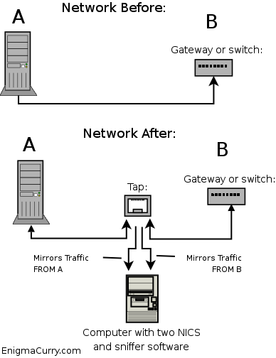
In the above diagram, A is a single computer (or it could be a switch) and B is a switch (or it could just be another computer, it doesn't really matter what these devices are). The Tap splits the connection between A and B. The connection inside the box is unbroken, that is, A is still physically attached to B. However, along the way, the transmit lines of A get mirrored as well as the transmit lines of B. These mirrored data lines are taken to a computer with some sort of sniffing software installed. Using a Tap requires the sniffing computer to have two network cards. One for A's transmissions and one for B's. So as to completely isolate the sniffer computer from the network, the sniffer's transmit lines are not connected. The sniffer computer can only "see" the data but can't "touch" it, effectively making the sniffer computer invisible on the network.
Building an Ethernet Tap
The Ethernet Tap is a passive device, it requires no external power. It's just a bunch of wires in a specific configuration. You can easily make this device yourself for less than 20 US FRN (btw, that's 20 US Federal Reserve Notes, not dollars, I call a spade a spade. Read about weights and measures in the US constitution and you'll understand why.)
I decided to make one myself and here is the parts I acquired from Home Depot:
- 4 category 5e network jacks. I actually bought a box of ten, they were cheaper that way. (3 FRN a piece)
- One four jack face plate (2 FRN)
- One blue electrical box (2 FRN)
- 6 inches of cat 5e cable (I actually just had this lying around)
Total: 16 FRN
The wiring is really quite easy. We have four ports. One that connects to host A, one that connects to host B and two tap ports. One tap port for all of host A's transmissions and one tap port for all of host B's transmissions. You wire host A to host B straight through pin for pin the same. Then just continue the transmission lines for each host down to the tap port for that host.
Here's a diagram (The dotted lines are the sriped wires, the sold colored lines are the solid colored wires):
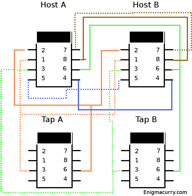
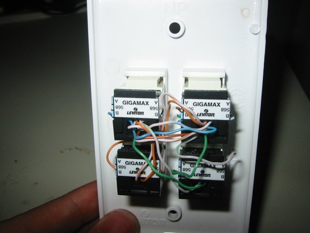
Strip the cat 5 cable and untwist all the individual wires. Place a jack in the upper left spot (from the front) in the faceplate. This is the Host A jack. Punch down all the wires for this jack with the little punch tool that came with it.

If you do one jack at a time it's easier:

Next put in a jack in the spot directly below it. This is the Tap A jack. Lace the orange wires from the host A jack to this jack and punch them down. You should still have several inches of the orange wires hanging off at this point. Now put in the host B jack to the right of host A. Lace all the wires except for the green ones (this includes the orange ones from Tap A) and punch them into the host B jack. Now without putting the tap B jack in the faceplate lace the green wires to it and punch them down, then lace the remaining length of green wires to the host B jack and punch them down there as well. Now put the tap B jack onto the faceplate.
At this point all of the wiring is done. You can now test to make sure it works. To protect the wiring, I wanted to put it in some kind of a box. I wasn't able to find a very good solution at Home Depot. What I did find though, was a blue electrical box that the faceplate would screw on to. It is MUCH larger than it needs to be, but it's not too bad looking (I'll probably look for a better box, or craft one of my own):
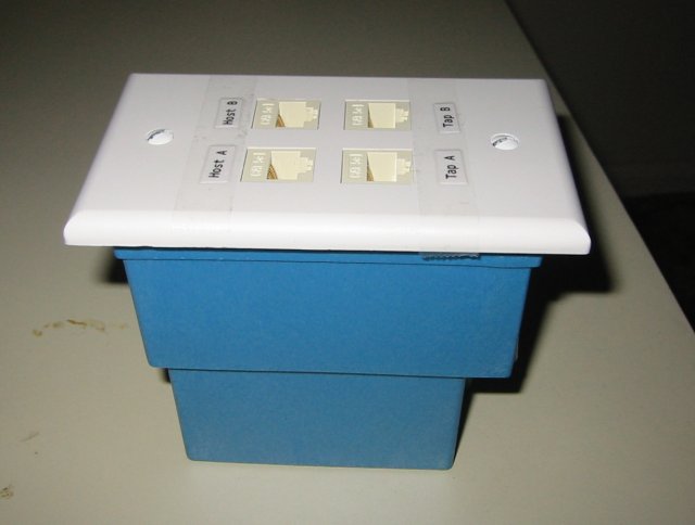
And there you have it, you're very own Ethernet tap.
Contact me
Friends
- brainjack>>
- Duane McGuire - My Dad
- Erin McGuire - My Sister
- Heavy Noir
- OneWatt
- Six Mile Village
Liberty Links
Categories
- android (rss) (1)
- backups (rss) (1)
- blogofile (rss) (1)
- car computer (rss) (1)
- cats (rss) (1)
- class work (rss) (1)
- cool stuff (rss) (9)
- curlbomb (rss) (1)
- diy (rss) (1)
- economics (rss) (2)
- electronics (rss) (1)
- emacs (rss) (13)
- enigma curry (rss) (8)
- enigmacurry.com (rss) (1)
- free state project (rss) (3)
- games (rss) (1)
- geek humor (rss) (3)
- geeky (rss) (2)
- gmail (rss) (1)
- gnome (rss) (1)
- hd-dvd (rss) (2)
- humor (rss) (2)
- java (rss) (3)
- letters (rss) (2)
- liberty rants (rss) (42)
- linux (rss) (20)
- lisp (rss) (1)
- michael badnarik (rss) (2)
- mitt romney (rss) (3)
- music (rss) (1)
- n800 (rss) (1)
- openoffice.org (rss) (1)
- php (rss) (1)
- pissed off (rss) (3)
- python (rss) (31)
- ron paul (rss) (9)
- security (rss) (5)
- software (rss) (1)
- stupidity (rss) (4)
- uncategorized (rss) (6)
- videos (rss) (9)
Archives
- May 2016 (1)
- July 2011 (1)
- September 2010 (1)
- July 2010 (2)
- April 2010 (1)
- January 2010 (1)
- December 2009 (1)
- July 2009 (1)
- May 2009 (2)
- March 2009 (1)
- January 2009 (4)
- December 2008 (3)
- November 2008 (2)
- October 2008 (1)
- September 2008 (1)
- August 2008 (3)
- July 2008 (1)
- May 2008 (2)
- April 2008 (2)
- March 2008 (1)
- February 2008 (2)
- January 2008 (1)
- December 2007 (1)
- November 2007 (5)
- October 2007 (7)
- September 2007 (3)
- July 2007 (3)
- June 2007 (3)
- May 2007 (3)
- April 2007 (3)
- February 2007 (2)
- November 2006 (1)
- October 2006 (3)
- July 2006 (1)
- June 2006 (1)
- May 2006 (2)
- April 2006 (10)
- February 2006 (2)
- January 2006 (6)
- December 2005 (1)
- November 2005 (5)
- October 2005 (3)
- September 2005 (2)
- August 2005 (5)
- July 2005 (1)
- June 2005 (2)
- May 2005 (7)